Brief Technical Summary
We construct an optically-efficient polarization field display by covering a stack of liquid crystal panels with crossed linear polarizers. Each layer functions as a polarization rotator, rather than as a conventional optical attenuator.
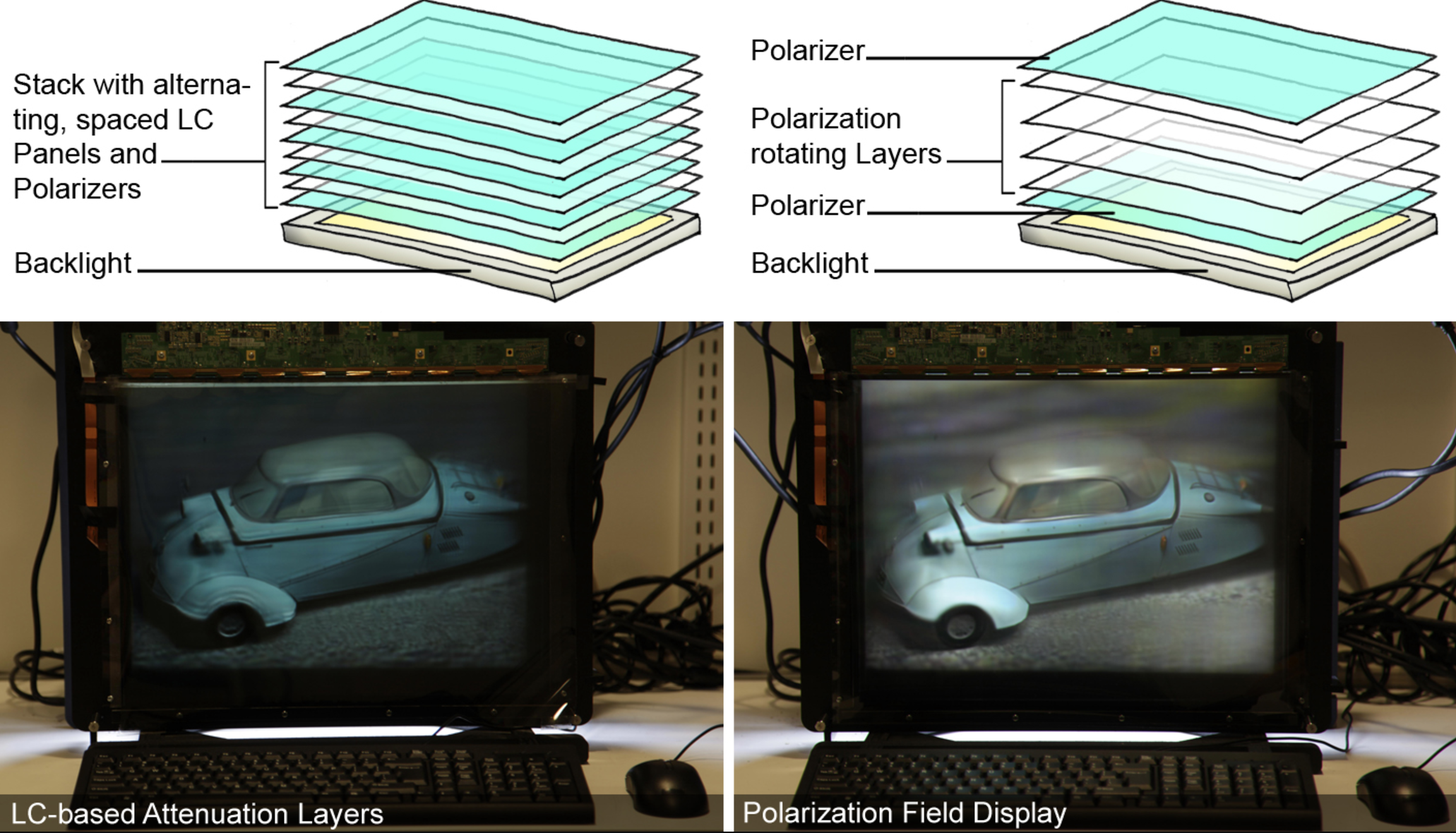
Polarization-based vs. attenuation-based multi-layer LCDs. (Top, Left) An attenuation-based light field display requires stacking liquid crystal panels with polarizers between each layer. This construction effectively creates a programmable transparency stack. (Top, Right) Polarization-based light field displays improve optical efficiency using a single pair of crossed polarizers. (Bottom) Corresponding photographs of the prototype configured as a an attenuation-based vs. polarization-based multi-layer LCD.
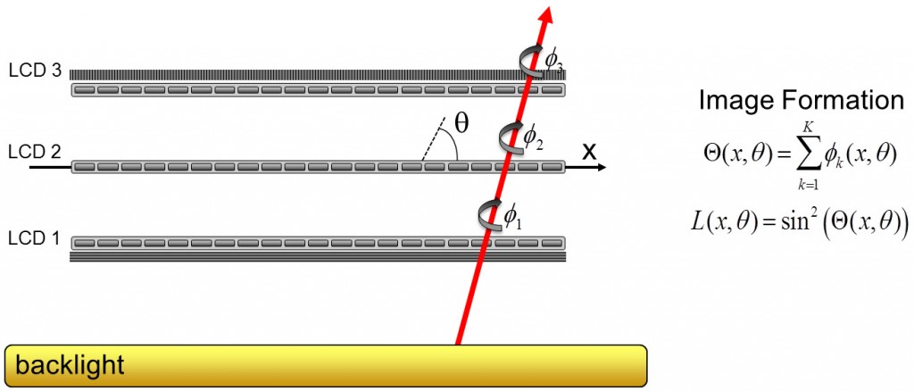
What’s special about this hardware design is that we only use two crossed linear polarizers around the entire stack (as opposed to one polarizer in between each LCD). Effectively, each pixel in the LCD stack acts as a programmable polarization rotator, as illustrated below. What comes out of the display (without the front polarizer) is what we call a polarization field – emitted light rays at different angles have all the same intensity but different polarization-rotation states. With the front polarizer inserted, this variation in polarization-state is optically converted into changes in intensity according to Malus’ law.
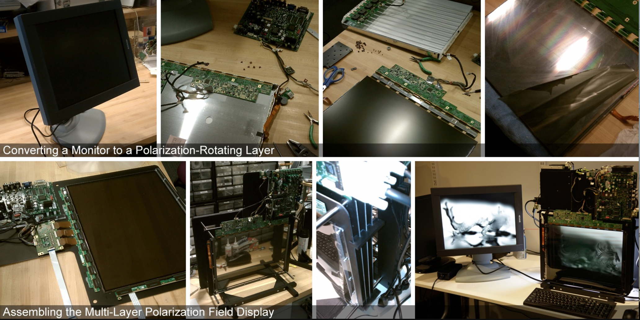
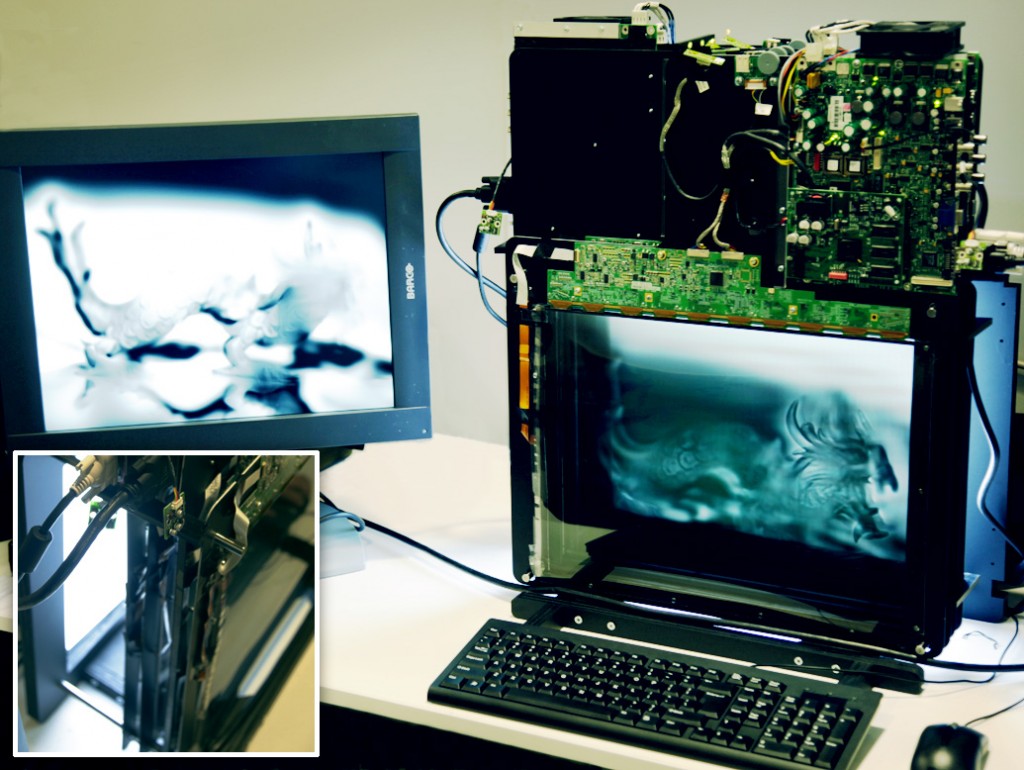
Constructing the polarization field display prototype. Four monochromatic, off-the-shelf medical LCDs were modified to create a single multi-layer LCD. Polarizing films were removed and electronics repositioned so the panels could be mounted on custom-fabricated frames. The layers are separated by acrylic spacers and illuminated by a uniform backlight.
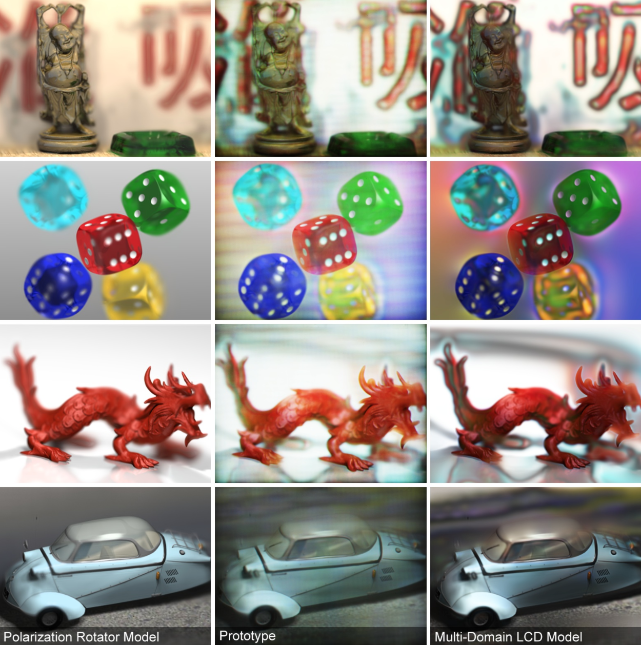
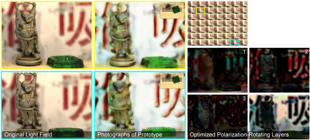
Polarization field display using multi-layer LCDs. The central views (i.e., those seen directly in front of the display) are shown for the “Buddha”, “dice”, “dragon”, and “car” scenes. The expected views, as predicted by the layered polarization rotator model and the layered multi-domain LCD model, are shown along the left and right columns, respectively. Corresponding photographs of the prototype are shown along the middle column. Color imagery results from combining three photographs taken while varying the color channel displayed by the monochromatic panels. Note that color artifacts and halos are more accurately predicted by the layered multi-domain LCD model; yet, overall performance is approximated by the layered polarization rotator model. With this approximation, dynamic display is feasible, at the cost of increased image artifacts.
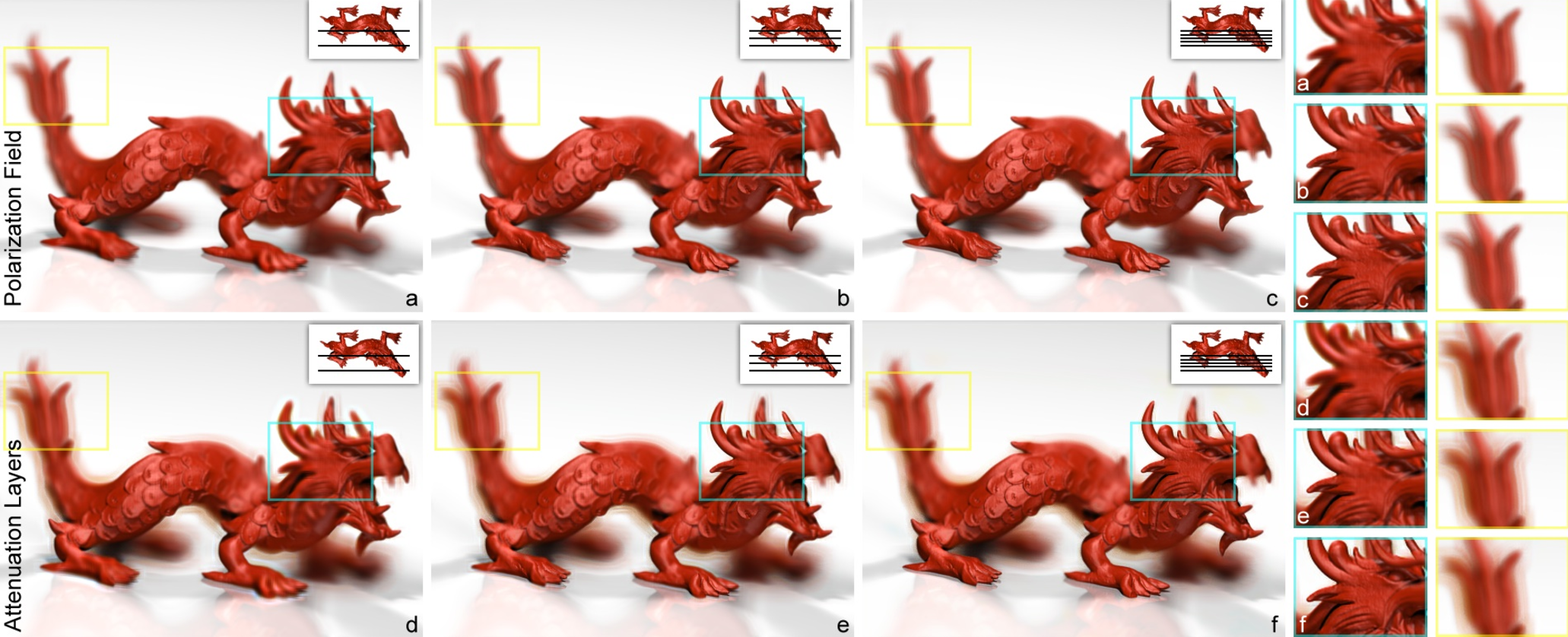
Comparison of polarization field display to “Layered 3D” (i.e., attenuation layers). Simulated light field reconstructions using polarization fields (top row) and attenuation layers (bottom row) are shown for two, three, and five layers from left to right. Layer positions with respect to the scene are illustrated in the insets. Note that the reconstruction fidelity of objects within and outside the physical display extent increases for a larger number of layers, as highlighted by the cyan and yellow regions, respectively. Due to bias in the least-squares solution for a log-domain objective, optimized tomographic reconstructions for attenuation-based displays suffer from halo artifacts around high-contrast edges, which is not the case for polarization field displays.
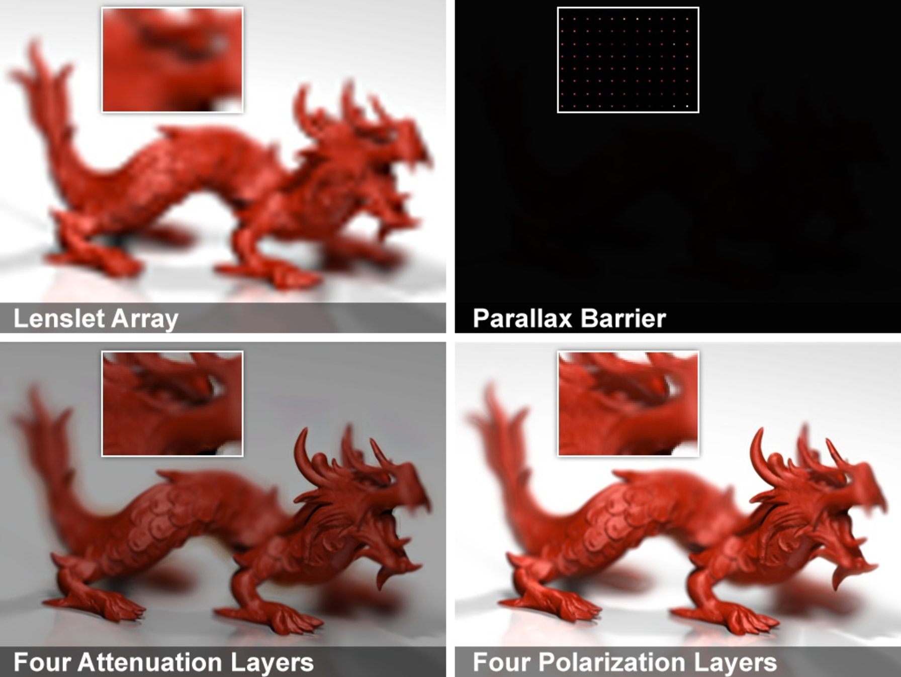
Benefits of polarization field display. Conventional glasses-free 3D displays employ either a lenslet array (top, left) or a parallax barrier (top, right) to project multiple viewpoints. As compared in the inset regions, parallax barriers consist of a uniform array of pinholes to support both vertical and horizontal viewer movement. As a result, parallax barriers severely reduce the brightness and resolution of the depicted scene. In contrast, “Layered 3D” (bottom, left) uses multiple attenuation layers to increase resolution and brightness, as compared to both lenslet arrays and parallax barriers. Yet, by optimizing the optical configuration of layered LCD panels, polarization fields (bottom, right) achieve further improvements in brightness and image fidelity.
Acknowledgments
We thank the reviewers for their insightful feedback and recognize the support of the MIT Camera Culture Group and the UBC Imager Laboratory. We also thank the MIT Media Lab sponsors. Douglas Lanman was supported by NSF Grant IIS-1116452 and DARPA Grant HR0011-10-C-0073. Gordon Wetzstein was supported by a UBC Four Year Fellowship. Wolfgang Heidrich was supported under the Dolby Research Chair in Computer Science at UBC. Ramesh Raskar was supported by an Alfred P. Sloan Research Fellowship and a DARPA Young Faculty Award.
